How to Create an Automatic Solar-Powered Street Light

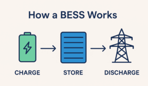
DIY photo voltaic mild tasks provide a cheap and environment friendly solution to energy properties utilizing power from the solar. So it is smart to assemble a avenue mild system that requires photo voltaic power to cost the battery through the day after which use this battery to mild the streets at night time. And you are able to do it your self!
An digital circuit controls this method, robotically turning on the LED bulb at night time and through the day. We will even embrace a battery safety circuit to guard the battery from over discharge.
What to Anticipate
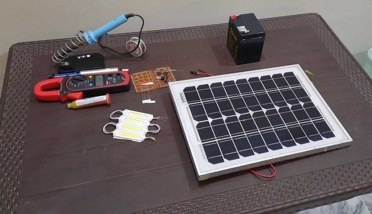
This technique requires 5 principal items:
- Photo voltaic panels: For charging the battery through the day and as a light-weight sensor.
- Battery: For saving the present and the powering circuit & bulb.
- LED DC bulb: For mild at nighttime
- Wires: For the interconnection based on the schematic diagram.
- Digital circuit: To robotically management/swap the LED bulb and for battery discharge safety.
Utilizing Photo voltaic Energy to Cost the Battery
For charging the battery, we used a small 10W (you’ll be able to select an even bigger one based on your finances/energy necessities) photo voltaic panel. It could possibly cost a 12V battery and supply 0.62A brief circuit present at peak luminosity. Its bodily dimension is about 12″ x 9″.

We’re utilizing a 12VDC battery with 4Ah capability now. Throughout the day, the photo voltaic panels generate present that’s used to cost the battery. The battery can have a most open circuit voltage of 13.7V at full cost and should be recharged when the battery voltage drops under 11VDC.
To cost the battery, the pink wire of the photo voltaic panel (constructive polarity) is linked to the constructive terminal of the battery by a Zener diode, which is offered on the Veroboard the place the digital circuit can also be positioned.
The Zener diode is positioned in such a method that the cathode (+ terminal) is linked to the photo voltaic panel and the anode (- terminal) is linked to the constructive terminal of the battery by wires. The Zener diode offers isolation between the photo voltaic panel and battery, which is particularly useful at nighttime when the circuit takes the voltage of the photo voltaic panel for switching the sunshine “ON”. The black wire (damaging polarity) is hooked up on to the damaging terminal of the battery.
When the photo voltaic panel is uncovered to daylight, it offers present to cost the battery, the quantity of which depends upon the depth of daylight. An LED bulb attracts present from the battery. The digital circuit controls the bulb utilizing sensor knowledge (photo voltaic panel voltage). Join the constructive terminal or cathode of the LED bulb to the constructive terminal of the battery, whereas connecting the anode of the LED with some extent c as proven within the schematics.
Digital Circuit Building
An digital circuit consists of two elements. One is supposed to regulate the LED bulb, whereas the opposite is supposed to regulate and stop battery drain.
Schematics of Automated Photo voltaic Avenue Mild
The determine under reveals your entire schematics of connecting this method. Construct the digital circuit for automated switching and battery drain safety on the Veroboard.

What You Want
The next instruments and elements are required for the digital circuit. You may get it from on-line shops like Digikey, Mouser or Ali Categorical.
- 1 x ULN2003 Darlington pair transistors IC
- 1 x LM7809 9 VDC voltage regulator IC
- 2 x LM393 Voltage comparator IC
- 1 x Veroboard (for connecting circuit parts by soldering)
- Resistors (in Ohms) 1K, 10K, 36K, 53K, 100K, 280K (Or an equal parallel/sequence mixture of those values)
- Wires
- Soldering iron and soldering wire
- Digital Multimeter (for voltage and present measurement)
- Screw terminals Block connectors (for connecting the wires to the photo voltaic panel, battery, and LED bulb)
- Zener diode (between pink wire of photo voltaic panel and battery + terminal)
LED Bulb Management
To modify the LED on at nighttime and switch it off within the daylight, use the photo voltaic panel voltage as a sensor to information the circuit. The photo voltaic panel and battery are remoted utilizing a Zener diode. The Zener diode is ahead biased in daylight as a result of the photo voltaic voltage will be increased than the battery voltage for charging, whereas it’s reverse biased at nighttime when no daylight is accessible to light up. of the photo voltaic panel, to offer vital output voltage.
On this circuit, the photo voltaic panel voltage is in contrast with the battery voltage utilizing a comparator. When it’s greater (throughout daylight), it offers the sign to show off the lights. Whether it is small, it alerts to activate the sunshine. The LED bulb is managed utilizing this logic and with the assistance of ULN2003 Darlington pair transistors. ULN2003 will get enter from comparator output. When it will get the sign for “On” on the enter pins (1-7) of the ULN2003 (ie from the comparator output pin 1), it permits the collector present to cross by C (Pins 10-16) to change the lights
To make this circuit, be a part of all of the circuit parts on the Veroboard by soldering. A Schmitt set off (constructive suggestions of the comparator) is applied within the LM393 comparator to stop glitches.
Avoiding Over-Discharge
If the climate is cloudy or foggy, it’s potential that the battery is probably not charged through the day, resulting in extreme battery discharge for a number of consecutive nights. This may trigger the battery to discharge to a degree the place the chemical steadiness of the battery is disturbed making it unavailable for additional use.
To guard the battery from over-discharge, one other comparator circuit utilizing the LM393 IC is proven within the schematics, which compares the battery voltage in opposition to a secure reference. For reference voltage, LM7809 voltage regulator is used, which takes battery voltage (ie 11 to 14 VDC) as enter and output is at all times 9V.
To make sure that the battery doesn’t exceed the deep discharge degree ie ~ 11V, use the comparator as a Schmitt set off. When the battery voltage drops under 11 volts, the Schmitt set off outputs a logic low which in flip disables the switching circuit. To make the switching circuit once more, it’s mandatory to completely recharge the battery to 13.2V.
You may make your individual selection of voltages (as a substitute of 11 V for low battery degree and 13.2V for charged battery degree) by selecting the suitable mixture of resistors (though that a lot deeper than we’ll study at current. ). For the battery safety circuit, join the circuit parts to the Vero board by soldering.
After making two automated switching and battery drain safety circuits on the Veroboard, lastly join these circuits, photo voltaic panel, bulb, and battery based on the schematic diagram.
Testing your Photo voltaic Avenue Mild System
To check the efficiency of this method, place the photo voltaic panel beneath daylight. You’ll be able to see that the LED bulb is “Off” with the publicity of the photo voltaic panel to daylight. Measure the voltage with a digital multimeter on the output of the photo voltaic panel and battery terminals. You will see that that the photo voltaic panel voltage is increased than the battery voltage. Now to verify if the battery is charging beneath daylight, use a digital multimeter to measure the present flowing by the battery.

Within the subsequent step, cowl the photo voltaic panel with a thick materials to dam the daylight and you will note the LED bulb mild up. Measure the voltage of the photo voltaic panel; you’ll discover that the photo voltaic panel offers a really low voltage that’s not sufficient for charging the battery. Then, measure the present from the battery to the LED bulb; you’ll be able to see that the bulb attracts present from the battery to provide mild.

Here’s a brief video demonstration of this take a look at:
Mild Up the Evening With the Mild of the Solar
This DIY challenge offers you the idea of creating a mini digital meeting for designing an automatic solar-powered avenue mild utilizing pure and renewable photo voltaic power. For max use of sources; choose the proper specs for the photo voltaic panel, battery, and light-weight bulb to make sure that the photo voltaic panel costs the battery sufficient to maintain the sunshine bulb on all night time.